ATN-01-01: Milikian Experiment
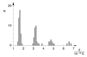
The electric field is calculated from the voltage U at the plate capacitor at which the observed oil droplet just begins to hover. The constant falling velocity v1 of the droplet when the electric field is switched off is subsequently measured to determine the radius. From the equilibrium between the force of gravity and Stokes friction, we can derive the equation.
Experiment:
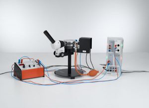
| ATN-01-01 | Determining the electric unit charge after Millikan and verifying the charge quantification – Measuring the suspension voltage and the falling speed with CASSY | |||||
| ATN-01-02 | Determining the electric unit charge after Millikan and verifying the charge quantification – Measuring the rising and falling speed with CASSY | |||||
ATN-01-02: Determining the electric unit charge after Millikan and verifying the charge quantification – Measuring the rising and falling speed with CASSY
The oil droplets are observed which are not precisely suspended, but which rise with a low velocity v2. Additionally, the falling speed v1 is measured, as in the variant P6.1.2.1 and P6.1.2.3. The measuring accuracy for the charge q can be increased by causing the oil droplet under study to rise and fall over a given distance several times in succession and measuring the total rise and fall times.
ATN-02: Thomson tube
ATN-02-01: Investigating the deflection of electrons in electrical and magnetic fields
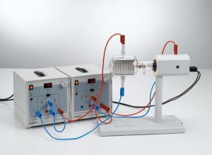
This experiment investigates the deflection of electrons in electric and magnetic fields. For different anode voltages UA, the beam path of the electrons is observed when the deflection voltage UP at the plate capacitor is varied. Additionally, the electrons are deflected in the magnetic field of the Helmholtz coils by varying the coil current I. The point at which the electron beam emerges from the fluorescent screen gives us the radius R of the orbit. When we insert the anode voltage in the following equation, we can obtain an experimental value for the specific electron charge whereby the magnetic field B is calculated from the current I.
ATN-02-02: Assembling a velocity filter (Wien filter) to determine the specific electron charge
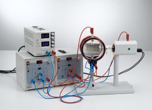
In this experiment, a velocity filter (Wien filter) is constructed using crossed electrical and magnetic fields. Among other things, this configuration permits a more precise determination of the specific electron charge. At a fixed anode voltage UA, the current I of the Helmholtz coils and the deflection voltage UP are set so that the effects of the electric field and the magnetic field just compensate each other. The path of the beam is then virtually linear,
Experiment:
| ATN-02-01 | Investigating the deflection of electrons in electrical and magnetic fields | |||||
| ATN-02-02 | Assembling a velocity filter (Wien filter) to determine the specific electron charge | |||||
ATN-03: Planck’s constant
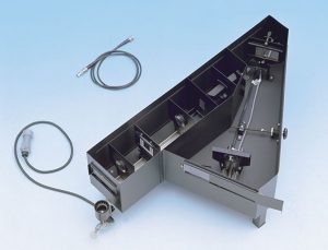
The Planck’s constant is one of the fundamental constants of physics which occurs in describing the quantum character of microphysical objects, as for example, electrons and photons. The Planck’s constant, therefore, occurs as fundamental constant in many experiments describing quantum behavior of nature. In this experiment the Planck’s constant h will be determined by means of the photoelectric effect.
| ATN-03-01 | Determining Planck’s constant – Measuring in a compact assembly | |||||
ATN-04: Paul Trap
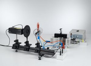
The experiment demonstrates how a Paul trap works using a model which can be operated with no special requirements at standard air pressure and with 50 Hz AC. When a suitable voltage amplitude U0 is set, it is possible to trap lycopod spores for several hours and observe them under laser light. Tilting of the entire ion trap causes the trapped particles to move radially within the ring electrode. When a voltage is applied between the cover electrodes, it is possible to shift the potential along the z-axis.
| ATN-04-01 | Observing individual lycopod spores in a Paul trap | |||||
ATN-05: Frank-Hertz
This experiment is offered in two variations, experiments ATN-05-01 and ATN-05-02, which differ only in the means of recording and evaluating the measurement data. The mercury atoms are enclosed in a tetrode with cathode, grid-type control electrode, acceleration grid and target electrode. The control grid ensures a virtually constant emission current of the cathode. An opposing voltage is applied between the acceleration grid and the target electrode. When the acceleration voltage U between the cathode and the acceleration grid is increased, the target current I corresponds closely to the tube characteristic once it rises above the opposing voltage. As soon as the electrons acquire sufficient kinetic energy to excite the mercury atoms through inelastic collisions, the electrons can no longer reach the target, and the target current drops. At this acceleration voltage, the excitation zone is directly in front of the excitation grid. When the acceleration voltage is increased further, the excitation zone moves toward the cathode, the electrons can again accumulate energy on their way to the grid and the target current again increases. Finally, the electrons can excite the mercury atoms once more, the target current drops again, and so forth. The I(U) characteristic thus demonstrates periodic variations, whereby the distance between the minima ΔU = 4.9 V corresponds to the excitation energy of the mercury atoms from the ground state 1S0 to the first 3P1 state.
Experiment:
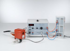
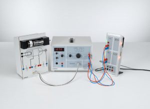
| ATN-05-01 | Franck-Hertz experiment with mercury – Recording and evaluation with CASSY | |||||
| ATN-05-02 | Franck-Hertz experiment with neon – Recording and evaluation with CASSY | |||||
ATN-06: Electron spin resonance
ATN-06-01: Electron spin resonance at DPPH – determining the magnetic field as a function of the resonance frequency
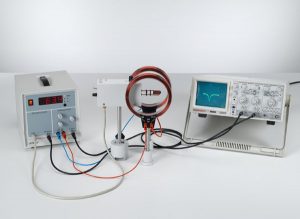
The experiment ATN-06-01 verifies electron spin resonance in diphenylpicryl- hydrazyl (DPPH). DPPH is a radical, in which a free electron is present in a nitrogen atom. In the experiment, the magnetic field B which fulfills the resonance condition the resonance frequencies n can be set in a continuous range from 13 to 130 MHz. The aim of the evaluation is to determine the g factor.
ATN-06-02: Resonance absorption of a passive RF oscillator circuit
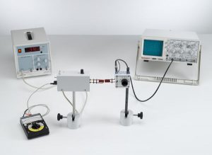
The object of the experiment ATN-06-02 is to verify resonance absorption using a passive oscillator circuit.
| ATN-06-01 | Electron spin resonance at DPPH – determining the magnetic field as a function of the resonance frequency | |||||
| ATN-06-02 | Resonance absorption of a passive RF oscillator circuit | |||||
ATN-07: Physics of the atomic shell
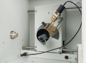
ATN-07-01: Bragg reflection: diffraction of X-rays at a monocrystal
| ATN-07-01 | Bragg reflection: diffraction of X-rays at a monocrystal | |||||
| ATN-07-02 | Investigating the energy spectrum of an X-ray tube as a function of the high voltage and the emission current | |||||
| ATN-07-03 | Duane-Hunt relation and determination of Planck’s constant | |||||
| ATN-07-04 | Edge absorption: filtering X-rays | |||||
| ATN-07-05 | Moseley’s law and determination of the Rydberg constant 8 | |||||
ATN-08:X-ray energy spectroscopy
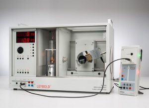
ATN-08-01: Recording and calibrating an X-ray energy spectrum
ATN-08-02: Recording the energy spectrum of a molybdenum anode
ATN-08-02: Recording the energy spectrum of a copper anode
ATN-08-04: Investigation of the characteristic spectra as a function of the element’s atomic number: K-lines
Experiment :
| ATN-08-01 | Recording and calibrating an X-ray energy spectrum | |||||
| ATN-08-02 | Recording the energy spectrum of a molybdenum anode | |||||
| ATN-08-03 | Recording the energy spectrum of a copper anode | |||||
| ATN-08-04 | Investigation of the characteristic spectra as a function of the element’s atomic number: K-lines | |||||
| ATN-08-05 | Investigation of the characteristic spectra as a function of the element’s atomic number: L-lines | |||||
| ATN-08-06 | Energy-resolved Bragg reflection in different orders of diffraction | |||||
ATN-09: X-ray tomography
ATN-09-01: Measurement and presentation of a computed tomogram with the computed tomography module
Experiment:
| ATN-09-01 | Measurement and presentation of a computed tomogram with the computed tomography module | |||||
| ATN-09-02 | Computed tomography of simple geometrical objects with the computed tomography module | |||||
| ATN-09-03 | Medical basics of computed tomography with the computed tomography module | |||||
| ATN-09-04 | Determining absorption coefficients and Hounsfield units with computed tomography with the computed tomography module | |||||
| ATN-09-05 | Computed tomography of biological samples with the computed tomography module | |||||
ATN-10: Rutherford scattering
Experiment:
| ATN-10 | Rutherford scattering: measuring the scattering rate as a function of the scattering angle and the atomic number | |||||
Video:
[embedyt] https://www.youtube.com/watch?v=945DHCzXrRo[/embedyt]
